

At a municipal wastewater plant in Jiangsu, operators watched effluent suspended solids climb from 25 mg/L to nearly 60 mg/L over the course of a month. The biological process seemed stable, and chemical dosing remained unchanged. The real cause only showed up during a basin inspection: a worn scraper blade on the secondary clarifier had allowed sludge to pile up unevenly, creating dead zones that disrupted the settling profile. That single mechanical issue pushed effluent quality outside permit limits. It is a reminder of how central the clarifier is to wastewater treatment, even when it looks like a quiet, static structure in the process train.
What Is a Clarifier and How Does It Work?
A clarifier is a large sedimentation tank that separates suspended solids from wastewater using gravity. The feed stream enters through an inlet structure and passes into a central feed well. In the feed well, the forward velocity of the incoming water is reduced enough to allow particles to begin their descent. The water then spreads outward and upward. As it travels across the tank, suspended particles drop to the floor, and the clarified effluent reaches a peripheral overflow weir. A rotating scraper mechanism pushes settled sludge toward a collection sump, where it is withdrawn for downstream thickening and dewatering.
The clarifier does not convert or consume contaminants. It is a physical separation unit, and its performance depends directly on how well the basin is designed and maintained. Circular and rectangular layouts are both common, but circular tanks are more frequently used in municipal applications because the rotating scraper and peripheral weir distribute flow evenly over a large area.
Primary vs. Secondary Clarification
Primary clarifiers are located after screening and grit removal and before the biological process. Their main purpose is to remove settleable organic solids and floatable oils and fats. At typical municipal design conditions, a primary clarifier removes 50-70% of incoming suspended solids and 25-40% of BOD. Removing that portion of the organic load before biology reduces aeration energy consumption and stabilizes the downstream process.
Secondary clarifiers sit after the biological reactor. They are used to separate the activated sludge biomass from the treated effluent and to return part of that biomass back to the reactor. The performance of a secondary clarifier is closely linked to the settling qualities of the biological sludge. A well-operated secondary clarifier can keep effluent suspended solids below 30 mg/L, with solids removal efficiency in the 80-90% range.
| Parameter | Primary Clarifier | Secondary Clarifier |
|---|---|---|
| Surface loading (m³/m²·d) | 30-50 | 15-25 |
| Detention time (h) | 1.5-2.5 | 2.0-4.0 |
| Solids removal (%) | 50-70 | 80-90 |
| Weir loading (m³/m·d) | 125-250 | 100-200 |
| Typical depth (m) | 3-5 | 3-5 |
Key Design Parameters That Determine Performance
Several hydraulic and mechanical parameters determine how a clarifier performs. The surface loading rate, also known as overflow rate, is the wastewater flow divided by the tank surface area. For conventional primary clarifiers, the accepted design zone is 30-50 m³/m²·d. The detention time, normally 1.5-2.5 hours for primary clarifiers, determines whether the smallest settleable particles have enough time to reach the floor. The weir loading rate, which falls between 125 and 250 m³/m·d in standard circular tanks, controls the upward flow velocity at the effluent boundary. Tank depth, commonly 3-5 meters, must provide enough volume for the sludge blanket and prevent the blanket from stripping under normal hydraulic peaks.
The mechanical side deserves equal attention. Scraper arms should turn no faster than about 1.5 revolutions per minute so that sludge is conveyed smoothly toward the sump without disturbing settling. The feed well needs to be sized to dissipate inlet velocity and create a calm zone. The effluent weir has to be level and evenly loaded. A weir that is out of level by even 1-2 centimeters can create local high-velocity strips that pull solids into the effluent.
Common Clarifier Problems and How to Diagnose Them
Clarifier problems are often not visible from the process control room. A rising sludge blanket in a secondary clarifier is frequently caused by denitrification. Nitrogen gas produced inside the biological floc lifts the sludge to the surface, and the blanket climbs or floats completely. Checking the dissolved oxygen in the aeration basin and the return sludge rate is the first diagnostic step.
In primary clarifiers, a thick scum layer can cover the skimmer and pass large amounts of floatable material through the tank. This is usually visible as foam or grease accumulation at the downstream screen or in the effluent. An unlevel effluent weir, an oversized feed well, or a damaged inlet baffle can produce short-circuiting, where the influent reaches the outlet in a fraction of the design detention time.
Preventive maintenance should include routine inspection of the scraper blades, weir plates, and skimmer. Worn rubber or polyurethane scraper blades need to be replaced once the gap between the blade and the tank floor becomes excessive, typically greater than 10-15 millimeters. Sludge pumps should be adjusted to hold the blanket at the design level. Pumping too little concentrates the blanket and risks solids carryover; pumping too much wastes sludge and raises the cost of downstream handling.
How to Choose the Right Clarifier for Your Plant
Clarifier selection should start with the hydraulic and solids loading values, not with a preferred brand or model. For sites with limited footprint, lamella plate clarifiers offer a compact alternative, but they respond poorly to large flow swings. Municipal plants above roughly 1,000 m³/h still rely mostly on circular clarifiers, where peripheral drive scrapers survive decades with modest maintenance. For municipal wastewater treatment applications, this is a well-proven arrangement. For smaller industrial or medium municipal applications, center drive scrapers can combine clarification and sludge thickening in a single tank, reducing the need for a separate pre-thickening step.
Consider how the clarifier integrates with the rest of the plant. A clarifier that discharges a thick sludge will cut polymer consumption and power use in the downstream dewatering process. The size and configuration of the feed well, the depth of the settled water zone, and the choice between peripheral and central drive scrapers are practical decisions that plant operators will live with for 20 years or more.
For large circular tanks, Qingben offers a peripheral drive mud scraper designed for diameter ranges common in municipal facilities. For tanks with a smaller footprint, a central drive mud scraper and thickener provides combined clarification and pre-thickening. If you are handling industrial wastewater with high suspended solids variability, an efficiency sedimentation tank process package may be more suitable.
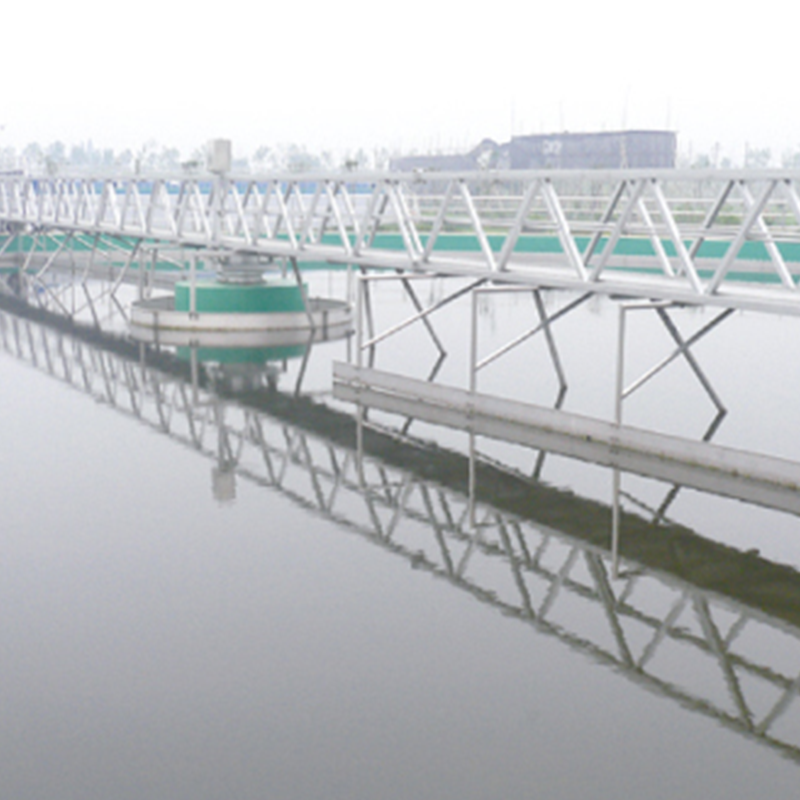 Peripheral Drive Mud Scraper for Large Circular Tanks This scraper suits large circular clarifiers, typically over 20 m in diameter, and uses a logarithmic spiral blade to prevent jamming. It is designed to handle high water volumes while protecting the drive mechanism from overload. View Product →
 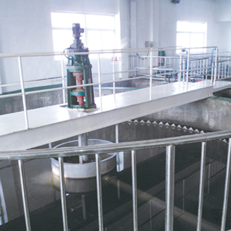 Central Drive Mud Scraper and Thickener for Smaller Clarifiers Ideal for circular tanks under 18 m, this unit combines sludge scraping with pre-thickening. It features an adjustable rake arm and optional automatic lift, making it adaptable for municipal wastewater with light sludge. View Product →
 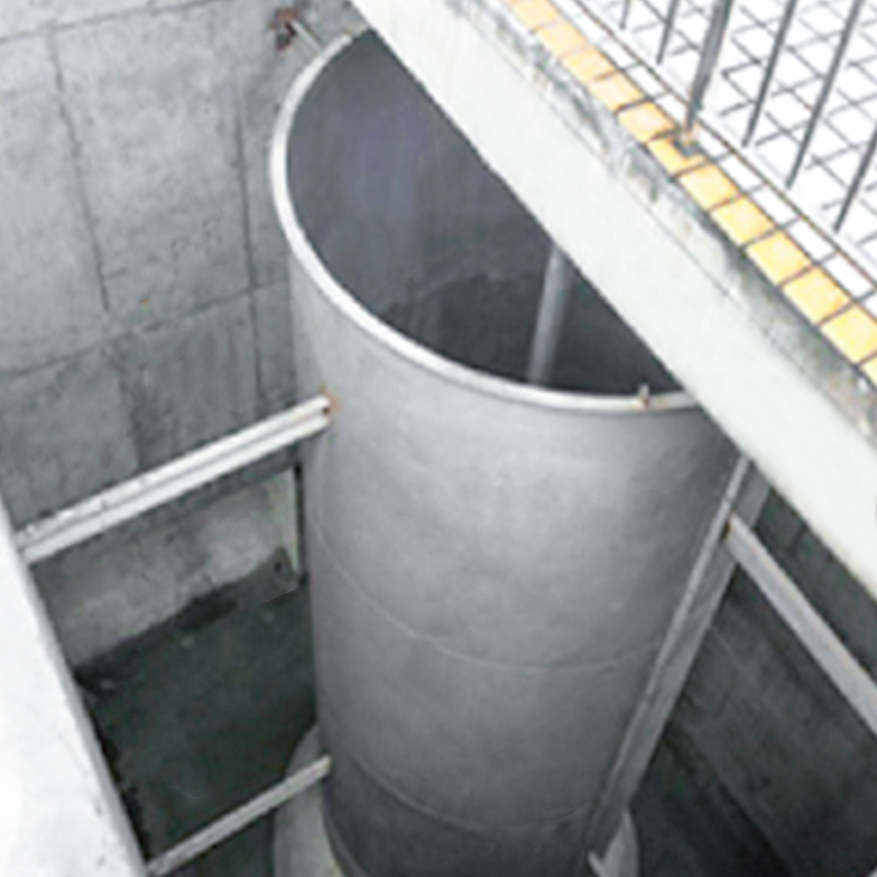 High-Efficiency Sedimentation Tank Process Package This package integrates flocculation and inclined plate settling to achieve high-density sludge and clear effluent in a compact footprint. It reduces chemical usage and enhances removal of suspended solids, algae, and phosphorus. View Product →
 Frequently Asked Questions
Q1: What is a clarifier in wastewater treatment?
A clarifier is a gravity settling tank that removes suspended solids from water. It is used in both primary and secondary treatment stages to produce clarified effluent.
Q2: What is the difference between primary and secondary clarifiers?
Primary clarifiers settle raw solids before biological treatment. Secondary clarifiers separate biological solids after treatment. They operate at different points in the treatment train.
Q3: What is the typical suspended solids removal in a primary clarifier?
Under common municipal design conditions, a primary clarifier removes 50-70% of incoming suspended solids and 25-40% of BOD.
Q4: Why does the sludge blanket rise in my secondary clarifier?
A rising blanket usually means denitrification. Nitrogen gas bubbles in the sludge cause it to float. Check the return sludge rate, DO levels, and sludge retention time.
Q5: What are the key design parameters for a clarifier?
Surface loading rate, detention time, weir loading rate, and tank depth. Typical primary clarifier ranges are 30-50 m³/m²·d, 1.5-2.5 h, 125-250 m³/m·d, and 3-5 m.
Q6: How do I choose between circular and rectangular clarifiers?
Circular clarifiers are common in large municipal plants because of simple mechanics. Rectangular clarifiers suit constrained spaces and shared-wall construction. The choice depends on site layout and budget.